Steve
Society Members
vintageradio.co.nz
Posts: 727
|
Post by Steve on Jun 8, 2021 21:55:32 GMT 12
So I have a new Pacific that has come to stay, and its an interesting set in its own right - 1932 date code, which is a year before the Pacific Radio Company Ltd was even registered as a company - and it appears to be close to a Courtenay 5B schematic. Up until now I thought this cabinet style was only for 7-valve BC sets - but I got two 5V versions in this cabinet together - the other one is different though, with a different lineup 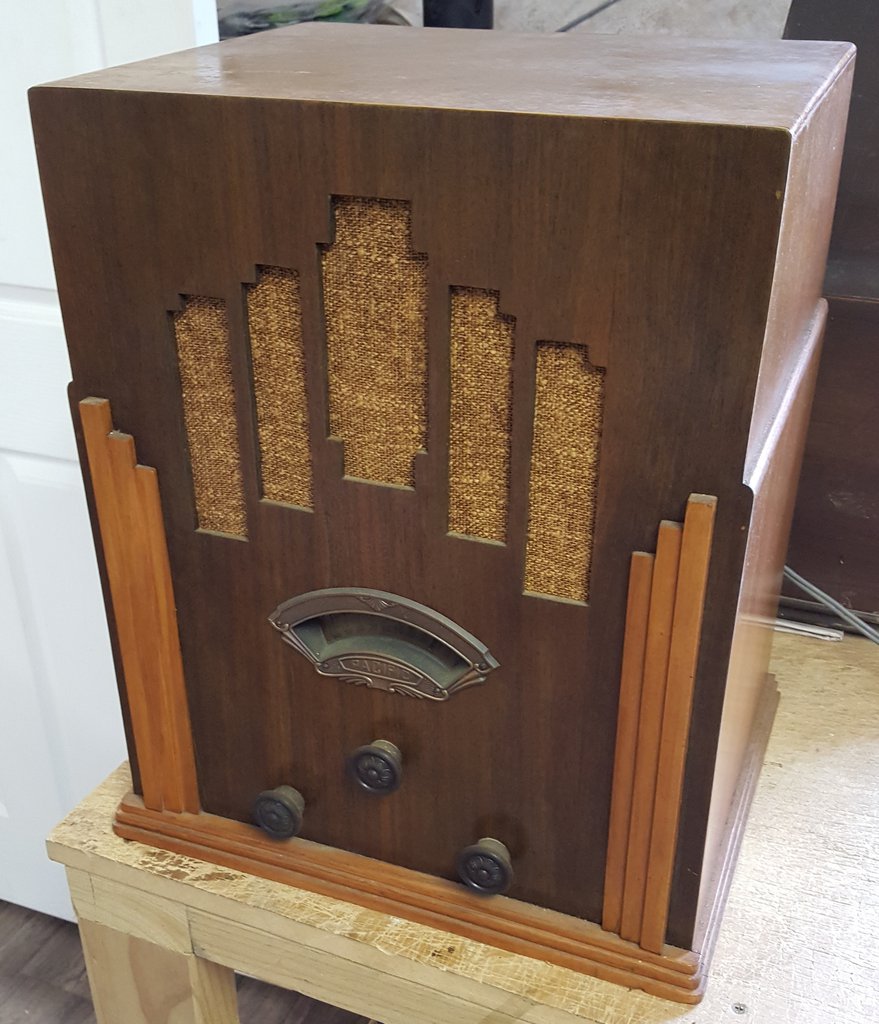 This is not the actual set, but this style of cabinet. I've modified a Courtenay 5A schematic to suit my set - and I have some questions.  Pacific version  Courtenay version It works (now)... it required a LOT of new caps (all of them), several new resistors and a new power transformer which was knackered (see part 2 of my dim bulb tester build video - coming to a theatre near you soon). But its working. Although the volume is only working in the last 5-10% of the pot (I'm wondering if the 50k pot in it is actually supposed to be 10k like the original 5B schematic suggests). I've also got fading, quite bad, rolling in and out but I'm putting this down to no AVC - most of my collection (in a working state) is 1935-onwards and so all of those sets have AVC. I'm also slightly confused by the 50k resistor down the bottom off the end of the volume control to HT... which puts it in parallel with the two 25k resistors also off the end of the volume control across the screen grid feed. This is not quite like the Courtenay circuit. But then this one has a 58 as a detector, not a 24. The set has had a LOT of work, and so I'm not sure that everything is actually in the right place. Now, on that 58 I'm not totally sure it should be a 58 - thats just what was in it. I've seen instances of 57's being used as a detector before but not a 58. And - the astute among you may have noticed the voltages I drew on the circuit - those are as-measured while on station and near full volume (which is not that full, its just where it needs to be to hear anything even with my long-line aerial hooked up)... the plate voltage of the detector 58 runs between 15 and 20V depending on volume level. Can anyone explain that to me? I have theories but nothing that makes sense Cheers, Steve |
|
|
|
Post by elorens on Jun 8, 2021 22:57:47 GMT 12
Steve, I agree that the 50k seems superfluous here, given the two 25k resistors. It would be great to hear from someone who really understands what is going on in the circuit. Am I right in thinking that the volume control will also affect front-end selectivity?
|
|
DHockey
Society Members
Posts: 140
Member is Online
|
Post by DHockey on Jun 9, 2021 9:20:41 GMT 12
Hi Steve
This set uses an Anode Bend detector also called a plate detector, which is essentially an audio amplifier biased almost to cut-off. When the output from the 2nd I.F arrives at the grid of the detector tube the negative half cycle of the waveform will drive the tube further into cut-off while the positive half cycle will turn the tube on, causing the signal to be demodulated. That is how I understand an Anode Bend detector to work. To work properly a Sharp Cut-off pentode like the 57 needs to be used as opposed to the remote cut-off 58. Are there any signs of a socket change? I’m suspecting your set originally had a 224 sharp cut-off tetrode like in the 5B circuit.
I recently finished working on a CQ model 51 which uses a similar circuit with a 57 detector / 1st audio, when testing I measured closer to 200V on the plate of this tube. Incidentally, this set uses a 10k (linear) volume control which seems to work quite well with a decent aerial connected.
I can’t really add much on the two 25k resistors that are part of the screen grid circuit, not really sure what is going on there. The CQ 51 has a similar arrangement but with two 50k resistors, but one of them terminates to ground rather than the volume control. I assume it is just a voltage divider to derive the correct screen grid voltage.
|
|
|
|
Post by Richard on Jun 9, 2021 13:00:01 GMT 12
Anode Bend Detection.pdf (824.12 KB) Anode bend detection was ok in the early days of broadcasting, when there wasn't much music , but mainly voice, you might be disappointed in the amount of distortion this type of detection introduced, have a read of this article, you may want to modify the circuit? I'm also confused by the 50k across the 2 X 25K screen grid voltage divider resistors, have you tried removing it?
|
|
DHockey
Society Members
Posts: 140
Member is Online
|
Post by DHockey on Jun 9, 2021 15:29:58 GMT 12
Anode bend detectors don't cope well with two things; high levels of modulation and music. Those two things are prevalent nowadays in AM broadcasting. The radios that I have with anode bend detctors do exhibit noticable distortion. But the problem goes away when I feed a signal via my low power SSTran transmitter where I can vary the modulation level. So I primarlly use these radios for listening to podcasts etc via the transmitter.
Despite the drawbacks, I quite like the anode bend detector, its a clever bit of design from the early days of radio which was only used for a few years before the double diode tubes came along. #savetheanodebend!
|
|
Steve
Society Members
vintageradio.co.nz
Posts: 727
|
Post by Steve on Jun 9, 2021 16:34:09 GMT 12
Thank you for the education Daniel and Richard  Its a new era for me... I'm slowly working my way back through the 30's and will soon be looking at breadboards with basketweave coils and 01A's on them Richard, that article is very helpful and very interesting - I won't be converting it though - I'll try to make it as original as is possible. I have radios with better audio circuitry for music - I'd rather it was original (ish) in this instance... and actually (weirdly, perhaps) I don't mind a little distortion as it adds to the feeling and atmosphere of an old set.  Comparing the two circuits side by side, its interesting to see the Courtenay has 20k from the screen grid feeding the wiper of the volume control, the Pacific 50k from the HT feeding the end, so a fixed voltage on the coils as opposed to the Courtenay with a variable voltage. I will measure the voltage on the aerial out of interest. I did note this set was picking up 'clicks' from our electric fence which most sets don't as its not a high power one. I note with interest, something that I had not checked was the Courtenay 5C schematic 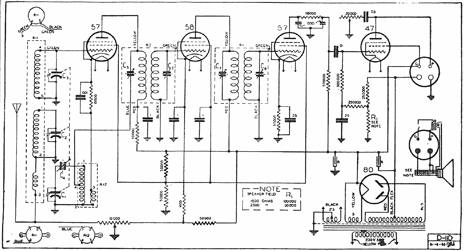 This is actually a lot closer to the Pacific I think - I might drop a 57 in the detector spot just to see how it performs... but the audio quality is not that horrible until you turn it up. And this has the 50k in the same spot as the Pacific, albeit a more sensible (to my way of thinking) 25k/25k voltage divider from ground feeding the screen grids. I might try this arrangement in mine as well to see what difference it makes. I'm still a little confused by the 15-20V on the detector plate though... its like the valve is acting like an almost short cct, only dropping 2V... (full turned on and conducting hard out? But its still making audio? And its not getting noticeably hot)... I'll ignore it while I play with the valve and a few other things. Cheers, Steve |
|
Steve
Society Members
vintageradio.co.nz
Posts: 727
|
Post by Steve on Jun 9, 2021 16:47:19 GMT 12
Quick update - I dropped a 57 directly in place of the 58 - WORLDS different. Volume control is now operational across almost the full range of travel, and its louder. I've now got between 17.5V and 35V on the detector plate, low volume to high respectively.
I will continue to play
Cheers, Steve
|
|
Steve
Society Members
vintageradio.co.nz
Posts: 727
|
Post by Steve on Jun 9, 2021 19:41:33 GMT 12
Ok, so I've been experimenting with the cathode bias resistor on the newly fitted 57...
increased 10k (as fitted originally) to 22k. Volume decrease, distortion high, sensitivity crap, plate voltage up to around 100V though
tried the two together, 32k. Volume big increase (slightly better than the 10k setup), sensitivity up, distortion down, plate voltage around 160V
tried 47k, as per the 5C circuit - Volume through the roof, volume control fully functional across the full rotation - it the top end I thought I was going to blow the cone out of the basket! Plate voltage around 190V
So, the detector circuit was suffering from multiple misdoings - and it might still be a ways away from perfect, but its working pretty darn good now and I've got to say it sounds quite good too.
What I don't have is any response from the top end of the dial - I'm good to around 1200kc/s then goes silent so I'll start playing around with that now - it could be alignment... I'm assuming this is 175kc/s in the IF, and I'll have to experiment with the other trimmers. I'm assuming the middle section of the gang is likely to be the preselector? I'll keep reporting back on progress...
Cheers, Steve
|
|
Steve
Society Members
vintageradio.co.nz
Posts: 727
|
Post by Steve on Jun 9, 2021 20:33:33 GMT 12
Ok, IF's were down around 160, but not fully peaked together... bringing those all on to 175 improved things significantly - a couple of turns on each trimmer almost. The oscillator padder was hard to get right because its very stiff and a metal screwdriver was the only thing that would turn it - and that pulled it off frequency... but I got there, and managed to then tune the top end to reach just over 1500 - which is 100 short of where I'd like to be since The Coast is around 1598 here in Chch... but I'll take the win.
So - at this point I'm pretty happy with it - most local stations are now too loud to go much past about 10% on the volume control (which is a big turn-around from where I was 24 hours ago!). I took a short video of it in operation - I'll upload that and link it in shortly. But compared to what I am used to in terms of poor reception from 5-valve sets out here in the country I'm a little blown away by this set. I wasn't expecting much, but it has delivered in spades. And I'm sure there is more to wring out of it yet with some fine tuning of component values and voltages... although I suspect I'm in the realm of 'diminishing returns' now.
Cheers, Steve
|
|
Steve
Society Members
vintageradio.co.nz
Posts: 727
|
Post by Steve on Jun 9, 2021 22:43:44 GMT 12
|
|
|
|
Post by Richard on Jun 10, 2021 9:28:36 GMT 12
Fantastic, you've probably got better low frequency response with this radio ? due to only 1 coupling capacitor in the a.f signal path. As Daniel mentioned a sharp cut off tube biased to near cutoff to achieve detection.
|
|
Steve
Society Members
vintageradio.co.nz
Posts: 727
|
Post by Steve on Jun 10, 2021 16:02:07 GMT 12
Its all back together now - very susceptible to LED driver noise, so this isn't the best location for it - but its where I am most likely to be standing around listening to the radio One thing I've discovered is that 3m of wire is enough, but also not nearly enough. The longline aerial at my service bench is much much (much) much better... It can stay here until it gets restored (or until I'm told to move it somewhere else)  |
|
|
|
Post by dada on Jun 10, 2021 16:14:29 GMT 12
I'd love that - a radio powered coffee machine! Well done, Cheers, DC
|
|
Steve
Society Members
vintageradio.co.nz
Posts: 727
|
Post by Steve on Jun 10, 2021 23:04:50 GMT 12
 Just out of interest, this is my set, and also my set - on the left is the Pacific, and on the right is a Courtenay 5C chassis which has had a lot of work - but its quite clear they are both very similar, and the chassis metalwork is almost identical as well. ...so if I'd looked a little harder (at my own collection!) when trying to work out what the chassis was I would have figured it out... but regardless, I got there in the end Here is a fairly original 5B chassis out of interest:  Its interesting to note that the 5B chassis is very similar but has a component board mounted diagonally in the middle. I originally thought this might be the difference, but the mounting holes and space are identical on the other two, so the board could have just been removed - which would explain the incredibly untidy layout in the Pacific. I believe from what I've read that the only real difference between the B and C is the valve lineup and a few slight circuitry differences Attachments:
|
|
|
|
Post by elorens on Jun 11, 2021 0:02:08 GMT 12
Quick update - I dropped a 57 directly in place of the 58 - WORLDS different. Volume control is now operational across almost the full range of travel, and its louder. I've now got between 17.5V and 35V on the detector plate, low volume to high respectively. I will continue to play Cheers, Steve What I need is a tutorial. What is the appeal of having a volume control here, rather than in the 'conventional' place? And how exactly does it work? It seems to me that multiple things are going on as you adjust that control. It would be good to have the full story on this since I have a similar set which eventually I will get to work on. Cheers, Lawrence |
|


 Its a new era for me... I'm slowly working my way back through the 30's and will soon be looking at breadboards with basketweave coils and 01A's on them


