6A8G.
Society Members
Hard working kiwi soundmixer.
Posts: 69 
|
Post by 6A8G. on Feb 15, 2022 10:34:39 GMT 12
Photos for last post<button disabled="" class="c-attachment-insert--linked o-btn--sm">Attachment Deleted</button><button disabled="" class="c-attachment-insert--linked o-btn--sm">Attachment Deleted</button><button disabled="" class="c-attachment-insert--linked o-btn--sm">Attachment Deleted</button> Hi Wayne if you're referring to the green resistor, it does indeed resemble the dog-bone resistor but I think this is more likely to be a wire-wound beastie. If this is the case it's likely to be correct in value. |
|
Steve
Society Members
vintageradio.co.nz
Posts: 734
|
Post by Steve on Feb 15, 2022 10:35:34 GMT 12
visually I'd say that resistor looks like 1/2W or 1W - but if you *carefully* measure the voltage across it while the set is running on station, then use ohms law, you could work it out:
V = I x R (V in volts, I in amps and R in ohms) therefore I = V / R
so if the voltage across the resistor is, for example 10V: I = 10(V) / 100(ohms) I = 0.1A (or 100mA if you prefer - but it helps to keep it in A form) Then the power calculation
P = I x V
P = 0.1A x 10V
P = 1WSo you'd know that resistor would need to constantly dissipate 1W, and so a 2W resistor would probably be the minimum appropriate value You can do a quick shortcut here if you like doing maths for fun (or if you just happen to know this):
P = I x V and
I = V / R
therefore P = V / R x V or
P = V2 / R
P = 100 / 100 P = 1W
And for quick reference, there are charts of all the combinations you might need, and some you'll likely never need, all over the internet Either way, the answer for this example (you'll need to measure yours and do the sums for your actual case) is 1W of heat dissipation based on that voltage drop - if you put a 1W resistor in then it would run 'full-bore' which is never a good idea - I'd double it or sometimes even triple it depending on what it was for.
CAVEAT: There are some circuits - some Philips ones in the 60's spring to mind - where resistors are also used as pseudo-fuses - they're designed to burn out in certain circumstances to protect the rest of the circuit - either a tight tolerance resistor is used, or a specifically designed 'fusable resistor'. I don't THINK this is the case here, but its worth keeping in the back of your mind.
As for the Philco 1257 - its probably similar to the 1256, which is likely the same set from the previous year(?) I don't know that I have seen one before so it might be a good one to add to the site:
The 2 and 3-way elecrolytics typically have shapes or colours associated with each tab showing what one has what value - check the side of the can for info on that.
Cheers, Steve
|
|
6A8G.
Society Members
Hard working kiwi soundmixer.
Posts: 69
|
Post by 6A8G. on Feb 15, 2022 11:03:29 GMT 12
Heh heh my Leak 20 amp uses the resistor "fuse" - it's a three-watt unit which is supposed to melt its solder connections in the event of an overload. Then it's supposed to drop off the circuit board thus breaking the HT line. Fun stuff!
|
|
wayne
Society Members
Posts: 142
|
Post by wayne on Feb 15, 2022 16:11:18 GMT 12
Thanks John
I understand about the values on the canned capacitor and the symbol to look for but they are hidden from view under the chassis. Reading my post back I could have explained it better 😊 is there a way of determining which tag the 20 is by what it's connected to ?
One tag goes to an EZ80 valve
One goes to the power switch volume and the other one goes to N78 valve
I don't want to remove the whole thing I've taken the top of and which to drill down and feed the cap wire's through to the tags left in place which I've done successful before.
Thanks again
Cheers
Wayne
|
|
wayne
Society Members
Posts: 142
|
Post by wayne on Feb 15, 2022 16:28:41 GMT 12
Thanks Steve the radio Philco 1257 is part of a Collaro radio gram I will send you some photos of the chassis but I have already replaced the caps apart from the one one I'm asking about
Cheers
Wayne
|
|
Steve
Society Members
vintageradio.co.nz
Posts: 734
|
Post by Steve on Feb 15, 2022 21:03:13 GMT 12
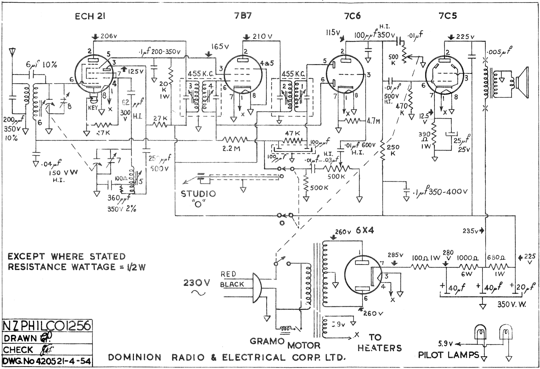 So, if we assume the 1257 is similar, if not the same, as the 1256 above (some resistor values might be different, but hopefully not too different). In the bottom right corner you can see the 40, 40, 20 electrolytic and how it is connected in the power supply part of the circuit. All three share a common ground, which is the case - it should be directly connected to the chassis. The first 40uF cap- is connected to the junction of the 100 ohm resistor (if its actually fitted) and the 1k 6 watt resistor (which will likely be quite sizeable)
- you could also find it by following the wire from pin 7 (cathode) of the rectifier valve, through the resistor, to it
The second 40uF cap- is connected to the junction of the large 1k resistor and a 680 ohm 1W resistor
- that large 1k resistor should be wired between the two 40uF caps - but because of its size it might not be directly connected to the cap itself
- it will also be connected to the output transformer
The 20uF cap - should be wired to the 680 ohm 1W resistor and, among other things, pin 3 of the 7C5 output valve
- also connected to a 250k resistor, a 0.1uF cap and the radio/gram switch
- The 680 ohm resistor will be wired between the second 40uF and the 20uF
This is all based on the schematic for a model which might not be the same - so you might need to wing it a little - but the power supply design is reasonably common in sets of that era so any differences should not be great. Its also all readable directly from the schematic - hopefully this makes sense and you'll be able to follow this as you read others in the future. Hopefully that helps. Cheers, Steve |
|
Steve
Society Members
vintageradio.co.nz
Posts: 734
|
Post by Steve on Feb 15, 2022 21:14:29 GMT 12
I just realised you added some info in a previous post - so here's some more info that might help.
the N78 is an output valve (a crap one in my limited experience with them) - so it's likely that the 20uF is connected to pin 7, the screen grid. The other two should be 40uF - one to the rectifier, the other to the output transformer
|
|
wayne
Society Members
Posts: 142
|
Post by wayne on Feb 16, 2022 21:16:06 GMT 12
Thanks Steve I appreciate the time you are spending on this
The valve info inside the cabinet is as follows
EZ80 EM80 ECH81 6BA6 6AT6 N78 now I cant find any markings on the first valve so will assume its a EZ80 but 2 of the others have been replaced at some time. the N78 to EL91 and the 6AT6 to EBC90
Just a thought and nothing more could it be that this model being being 1257 has had changes to it or some one like you who doesnt like the N78 has changed it
Thanks heaps for the Cap info I will print it off along with the schematic and use it to fit the new caps and let you know how I got on
Cheers Wayne
|
|
Steve
Society Members
vintageradio.co.nz
Posts: 734
|
Post by Steve on Feb 17, 2022 10:23:01 GMT 12
Ok, so it appears that the 1257 is a redesign and not like the 1256 at all. That's interesting, but for your current question what I said in the last post still applies.
As an aside, I don't think the EL91 is a direct equivalent for the N78 - but the screen grid pin number is the same - I expect the 20uF cap will be connected to pin 7 of that output valve.
I would also expect the middle 40uF cap to be connected to the output transformer, and the first 40uF cap to be connected directly, or perhaps via a low-value resistor, to the rectifier valve.
|
|
wayne
Society Members
Posts: 142
|
Post by wayne on Feb 17, 2022 20:30:00 GMT 12
Thanks Steve for your time and patients I will go with the 20 going to the N78, EL91 As I see it looking at the chassis one 40 goes to EZ80 ( rectifier ) via a resister that same valve connected to the mains transformer. My sketch in the picture as I see it from the chassis The other 40 appears to be connected to the output transformer and connected back to the other 40 What is a good replacement for the N78 ? Cheers Wayne  |
|
Steve
Society Members
vintageradio.co.nz
Posts: 734
|
Post by Steve on Feb 18, 2022 7:12:54 GMT 12
A couple of things -
1. hopefully you've just mislabeled it - but the N78/EL91 output valve should not be connected to the mains transformer that way - the rectifier should be.
2. If an N78 is working, leave it be. I don't like them because I've had nothing but trouble with them - but that doesn't mean you will too.
Can you check your diagram again? Is it just the two valves you have mislabeled? It was looking roughly what I would expect until I saw that bit...
|
|
wayne
Society Members
Posts: 142
|
Post by wayne on Feb 18, 2022 12:20:18 GMT 12
Yes I have labeled them wrong the EZ80 goes to the mains transformer
Thanks heaps
Cheers
Brian
|
|
wayne
Society Members
Posts: 142
|
Post by wayne on Feb 18, 2022 12:44:58 GMT 12
Is there a problem apart from what it looks like in fixing a tag strip on the top of the chassis for an earth to the electrolytic caps?
Cheers
Wayne
|
|
Steve
Society Members
vintageradio.co.nz
Posts: 734
|
Post by Steve on Feb 19, 2022 11:27:34 GMT 12
Why put it on top? I would generally try to avoid having anything related to the high voltage circuit on the top of the chassis. If you're using tag strip screwed to the chassis it might also be worth running a bonding wire from the mounting tag to a known good earth point on the chassis as well - I don't like to trust just the bonding between the tag strip mounting lug and the chassis.
|
|
wayne
Society Members
Posts: 142
|
Post by wayne on Feb 19, 2022 14:58:14 GMT 12
I've fixed the earth as you suggested and all good.
Now I powered it up with dim bulb tester and the bulb lights up but doesn't dim and there is no sounds at all, absolute silence. I don't know if this is a sign that the N78 valve is faulty but all the others I can see a light from them but not that one, it gets warm but doesn't appear to light up.
If I use an insulated screw driver with the shaft insulated as well if I poke around the tabs on that valve I can get a cracking sound from the speaker.
Thanks for any advice
Cheers
Wayne
|
|


